Quaketek Buckling Restrained Braces
Quaketek Buckling restrained braces are built with quality and cost in mind. Quaketek BRBs are used to provide structures with ductility based seismic protection.
What are Buckling Restrained Braces?
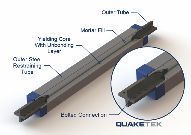
These braces are a structural element that, yield in both tension and in compression along their central axis (one direction). The principle of work is the same as that of a common diagonal element, but, in the case of a BRB without buckling in the braces. This quasi-symmetric yielding is accomplished by creating an element composed of a of steel plate (bar or others depending on the technology) covered by a mortar or concrete jacket through out its length. Although it looks like a composite element, an unbonding layer is added to the surface between the steel and the mortar/concrete allowing for tension forces to be developed only in the steel core, rather than a composite section. The unbonded layer is an important element of the BRB in order to prevent the section from acting as a composite element at significantly higher strength (which would be dangerous). In Compression, the steel core does not develop significant buckling, rather it deforms fairly uniformly along the covered length and the whole diagonal will be able to carry out a few cycles at full displacement before failure.

Design Approach for Buckling-Restrained Braced Frame
Depending on the seismic code philosophy, these elements function as either a sacrificial element to control damage or as a ductile main structural system (SFRS1). In standards that favor performance over plainly life safety,: these Buckling Restrained Braces are used in a “damage control” design philosophy where they are the sacrificial element in a structure with moment frames. In such cases, the structure is protected by sacrificing the brace and can have a very decent post-yielding stiffness, leading to a low level of damage. For example, in Japan, the design methodology uses these diagonal members to protect the primary system, the frames (Kasai, Fu and Watanabe 1998). Standards and codes of this style tend to use relatively low values of seismic response modification factors (e.g. R). In contrast, other standards, such as the American Code and those that draw upon it: apply a philosophy where the Buckling restrained Braces are the main structural system (SFRS), and thus, higher percentages of lateral deformation are expected. In these standards, the post-yielding stiffness expected is lower as the braces are not required to work in parallel with moment frames (Applied Technology Council 2015). Consequently, in these types of codes it is common to find more aggressive seismic response modification factor values, and the final performance of the structure tends to be as low as that of the rest of SFRS prescribed by those standards (Moment Frames, Shear walls, Braced frames etc.). In this second case, the engineer should consider the following minimum requirements for a safe implementation:
Minimum Requirements for seismic design of Buckling-Restrained Braced frames

These Buckling Restrained Braces are modeled as if they were connected to the structure with an ideal pin. Therefore, once the engineer has an estimate of the maximum drift (amplified by prescribed displacement factors, or through nonlinear analysis), they can use it to estimate what rotation will occur at the diagonal member from its initial angle. If the drift is close to, or greater than, two percent of the floor height, special care should be taken in the connection design. These diagonal bracing systems tend to suffer from failures due out-of-plane forces (Chien, et al. 2018) and allowing an unrestrained rotation capacity in the connection is essential. It is for this reasons that pin connections are preferred in these cases. The engineer could alternatively check whether the bolted connection allows this rotation demand in their actual installation configuration.
The maximum capacity of a Buckling Restrained Brace is approximately 2x above its design yield point (This varies somewhat tension and compression, and with the ratio between length, actual yield force, material properties, required displacement etc.). This makes this revision one of the most important because it establishes the capacity of the “load-path”. In other words, it defines the ability of a structure to transfer its forces, from any point to the foundation.
“For this load-path” to exist, ductility should only be present in the braces and in the columns (if detailed as highly ductile) but never in the connections or in the foundation. In the case of connections, these are of fragile failure, therefore ductility is not the most compatible, and in the case of foundations, the modeling of the structure with a Response Modification Factor (e.g. R) assumes a fixed base condition as the modeling hypothesis (ignoring soil-structure interaction effects); and for this condition to be met, the value of this factor should be revised when designing foundation elements and when estimating loads transferred to the soil, otherwise, the assumed energy dissipation capacity related to the factor could have been over-estimated. In this capacity design philosophy, the structure is allowed to dissipate energy inelastically while the foundation itself remains essentially elastic (NBCC 2015). Although this may seem complicated at first glance, it is relatively easy to check for this maximum shear, and even some standards already have general parameters for an indirect preliminary design, here two options:
Through Testing
The engineer can require that the manufacturer test a completed specimen of a representative force for the project (e.g. average of all project forces) up to the maximum drift limits that came out from the structural model. Although this is not a total sample of the entire project, as it would be expected on our higher performance devices (e.g. Ten-Co seismic brakes), this will give the engineer additional confidence with respect to what the maximum shear is and, in general, they can then have a more accurate estimate.
The only drawback with this option is that most manufacturers of Buckling Restrained Braces provide only a tension test report of a coupon, taken from the same heat at the steel plate from which the steel cores was cut from, or by providing some prototype test report (usually not performed for the project in question). This is usually the case because it is the minimum required by most standards, however, it leaves a fairly high margin of uncertainty on the force estimation. A note must be made in the sense that; such level of uncertainty is common in the industry as the rest of SFRS prescribed in standards don’t have additional quality controls either. Nonetheless, the engineer can require these tests since they are responsible for the design or more simply (albeit costly) design with larger overstrength factors (see next section).
Through prescribed factors in the standards
At the end of the day, the deformable core of the Buckling Restrained Brace is made of steel, and the properties of this material are well understood. Therefore, most standards give a fairly sound guidance that engineers can use to estimate this maximum shear for connections, columns and foundation design. In most of the standards, there is a prescribed Ω (omega) value for Buckling Restrained Braces and it is usually 2.5x. Then, the engineer can simply multiply the design shear by Ω and thus estimate the maximum shear for foundation design. In the same way, they can take the maximum axial force found in a diagonal brace and multiply it by Ω to find the design force of connections and columns.
In most standards that use aggressive response modification factors (e.g. R) strong limitations in the height of these systems are usually imposed, usually below 45m. This is essential because it is well known that bracing systems tend to accumulate permanent nonlinear lateral deformation as the height increases, and this can eventually lead to failure due to dynamic instability (Zieman 2010). This problem is easily solved by accompanying the Buckling Restrained Braces with high ductility moment frames that will help provide for decent post-yielding stiffness and not to accumulate non-linear lateral deformation.
The design of these diagonals assumes that, for tension forces, it will work as a steel plate (core) element, consequently this is the logic used for the revision of the maximum capacity. It would be very dangerous if, because of conditions of use, environmental, or poor manufacturing quality, the mortar, or any other material used for the outer jacket, to adhere to the steel core so that the Buckling Restrained Brace started behaving as a reinforced concrete element, or as a composite section. This would cause the maximum shear forces previously estimated to be considerably higher than those used for the design of connections, columns and foundation. This undesired effect would eventually lead to a catastrophic failure of the structural system as the “load-path” fails. Therefore, the engineer should require from the manufacturer to take on some kind of warranty at this point, or to require some kind of test protocol for the project that rules out those questions, or in the worst case, to assume such worst scenarios as input for the maximum capacity at the diagonal member and for the shear at the base.
