Earthquake protection technologies are used to control building damage during an earthquake. Today, the field of Earthquake Engineering is extensive and there are many ways to protect buildings against these seismic forces. More traditional methods tend to rely on ductility and damage, using the earthquake’s energy to deform metal or crack concrete, these are generally known as brute force and ductile approaches.
More sustainable technologies prevent earthquake damage by using seismic dampers or (non-ductile) base isolation. There are several types of seismic dampers but they all use some form of friction between solids (friction dampers) or within fluids (viscous dampers) to convert earthquake energy into thermal energy. Base isolation generally comes in three types, elastomeric, elastomeric with ductile energy dissipation and friction base isolators.
Below are some of the characteristics of various earthquake protection technologies. Please contact us with any questions you may have in choosing the best solution for your project.
Seismic Brake – Inline Friction Damper
The inline friction damper dissipates energy as the elements of the damper slide relative to one another in both tension and compression, converting an earthquake’s kinetic energy directly into thermal energy in a non destructive process. For a quick example, rub your hands together and you’ve just transformed a force through a distance (energy) into heat.
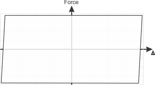
Constant Force Energy Dissipator
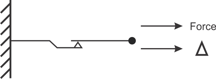
Benefits of Inline Friction Dampers
- Low cost of device and installation
- Allows for reduction in size of structural sections
- Easy to design with, not velocity or temperature dependent
- Rectangular hysteretic loop, highest (maximum) energy dissipation per cycle
- Maintenance free
- Can be installed in parallel to develop large loads
- Acts as a load limiting device (slip load limits buckling, column and foundation loads)
Disadvantages of Inline Friction Dampers
- Must reach slip load to dissipate significant energy
- Cannot be used to dissipate service loads (must set slip load higher than service load)
Outcomes of Poorly Designed/Manufactured Friction Dampers
- Friction force can change over time due to creep in the friction interface or creep in belleville washers
- Friction force can change over time due to corrosion
- Insufficient thermal mass (too lightweight a damper) or poor thermal conduction can result in large temperature increases.
- Significant velocity or temperature dependence could exist in cases where plastics are used in the interface
Testing Methods for Friction dampers
- 100% testing at full load and stroke.
- Sample testing (e.g 10% of a production run) can be used as a supplement but not as a replacement for 100% production testing.
- Testing should be done quasi statically in order to capture the change from static to dynamic friction as well as any variations in slip load in the damper travel.
Installation configurations
- Single diagonal
- Parallel (for larger loads)
- Chevron (at the top or in the diagonals)
- At beam/column connections
- Toggle
- Bolted, pinned or welded
Traditional Braces
Traditonal braces provide additional stiffness and therefore lateral resistance which helps buildings resist earthquakes via a brute strength approach. Conventional braces dissipate energy by yielding and strain hardening in tension and some energy is also stored/dissipated in compression through buckling .
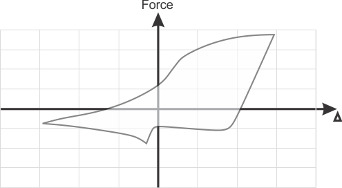
Assymetric Displacement Dependant Energy Dissipator

Main Benefits of Traditional Steel Braces
- Low initial cost of braces
- Easy to design with, not velocity or temperature dependent
- Many suppliers available
Disadvantages of Traditional bracing
- 100% testing is not possible
- Can only dissipate energy in tension, as buckles in compression
- Potentially requires strengthening of other structural members, as this increases rigidity, increases overall building cost.
- Require replacement after a major earthquake
Outcomes of poorly designed/manufactured braces
- Localized failures can occur if other structural elements aren’t reinforced to account for increased loads due to strain hardening in tension.
- Material yield points and material consistency is critical due to reliance on ductility. Variations can be problematic and should be tested for.
- Insufficient rotation at the gusset induces moments and leads to increased loads.
Testing Methods for Steel Braces
- 100% testing is not possible as it would be destructive and is not the current industry standard norm. Best practice would be to validate yield stress and material properties from mill tests.
- Verification braces dimensions match specifications and visual inspection to check for damage or manufacturing errors (e.g. splices).
Installation configurations
- Single diagonal (concentrically or eccentrically braced)
- Chevron (eccentrically or concentrically braced)
- Bolted, pinned welded to connection (normally welded)
Buckling Restrained Brace (BRB, unbonded brace)
Buckling restrained braces dissipate energy through yielding and strain hardening. As the earthquake causes forces to rise within the BRB the steel core starts to yield. As the core is prevented from buckling with its concrete/steel buckling restraint, the yielding is mostly symmetric in both tension and compression. For a quick example of the principal of ductile energy dissipation, take a paperclip and bend it back and forth, the energy input is used to deform the metal and you should be able to do several cycles and notice it harden before it breaks.
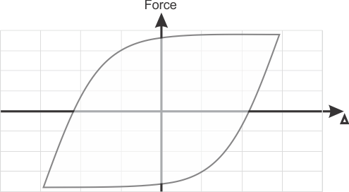
Displacement dependent yielding energy dissipator

Benefits of Buckling Restrained Braces
- Low cost of device
- Easy to design with, not significantly velocity or temperature dependent
- Prevents buckling of the brace (mostly symmetric in tension and compression)
- Potentially reduced number of braced frames required with respect to standard braces
Disadvantages of BRBs
- 100% production testing not possible
- Must reach yield force to dissipate significant energy, requires replacement after usage
- Requires strengthening of other structural members as increases rigidity, increasing overall building cost with respect to some other technologies.
- Large heavy elements can be difficult to install during retrofits
Outcomes of poorly designed/manufactured BRBs
- Insufficient space for yielding of steel core in the transition portion
- Too rapid a transition region
- Usage of incorrect material for steel core
- Bonding of steel core within the restrained area.
- Localized failures can occur if other structural elements aren’t reinforced to account for increased loads due to strain hardening.
BRB Testing Methods
- 100% testing at full load and stroke is not possible as it would be destructive. Coupon testing from each sheet from which the steel core is cut must be conducted to confirm material yield properties.
- Sample testing of 5-10% of a production run at full load and stroke (additional units would need to be manufactured)
- Best practice would be 100% testing of BRBs within their elastic range to ensure that they have the predicted stiffness.
Installation configurations
- Single diagonal
- Chevron
- Bolted, pinned welded to connection
Fluid Viscous Damper
Fluid viscous dampers, sometimes referred to as just viscous dampers use pressurized silicone fluid filled chambers to dissipate earthquake energy. As the piston slides back and forth within the cylinder the energy is transmitted to the silicone fluid and is converted to heat in a non destructive process. The reaction force will depend mostly on the velocity of the piston.
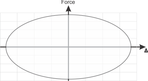
Velocity Dependent Seismic Damper
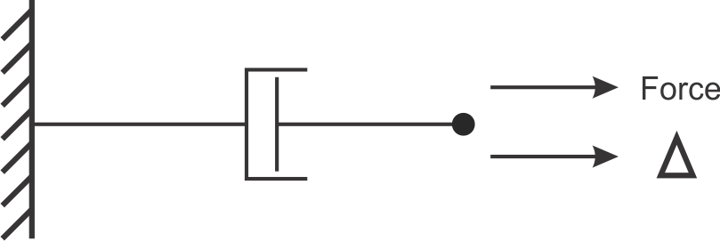
Benefits of Viscous Dampers
- Allows for reduction in size of structural sections
- Forces are generally out of phase (lowest force in damper occurs at zero velocity)
- Always dissipating energy and can dissipate wind energy
Disadvantages of Viscous Dampers
- High initial cost of the device
- Maintenance access required
- Change of damping force due to polymerization (hardening) of silicone oil has been observed
- More complex to integrate into designs due to velocity dependence
Outcomes of poorly designed manufactured Viscous Dampers
- Premature leakage around seals and loss of pressure
- Chipping/delamination of coating (when coating is used instead of polished stainless) on piston rod causing leak
Testing Methods for Viscous Dampers
- 100% testing at full load and stroke.
- Viscous Dampers must be tested at different velocities due to velocity dependance.
- Sample Testing can be carried out on a percentage of the dampers but not as a substitute for 100% production tests.
Installation configurations
- Single diagonal
- Chevron (at the top or in the diagonals)
- Pinned connections generally required
- Toggle
Elastomeric Base Isolation (Rubber, Lead Rubber Bearings)
How do Elastomeric Base Isolators work?
There are two main types of seismic base isolation elastomeric and sliding. Elastomeric base isolators act as springs (with damping in cases with yielding cores such as LRBs) which generally increase the period of the building and allow for reduced seismic design forces in the main structure. Generally, elastomeric base isolators are used with rigid short buildings. There are two main types of elastomeric base isolation, with and without a yielding core. In seismic applications, LRBs (Lead & Rubber Bearings) are most commonly applied. LRBs are elastomeric bearings with a yielding core made of lead surrounded by rubber layers which have been vulcanized onto steel plates.
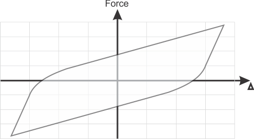
Spring with Metallic Yielding Energy Dissipator

Benefits of Base Isolation
- Can be used to increase building period for rigid buildings
- Installed below grade and does not take up valuable space
Disadvantages of LRB Base Isolation
- 100% production testing at full load and displacement is not possible
- High product and installation cost
- Must reach yield force to dissipate significant energy, requires replacement after usage
- Requires a gap around the base of the building for movement which adds to complexity especially in retrofits
- Stiffness of elastomers are highly temperature dependent. Stiffness increases at low temperatures while decreasing at higher temperatures.
- Specialty equipment and teams are required to install in existing buildings
- More complex to integrate into designs
Outcomes of poorly designed/manufactured LRBs
- Poor vulcunization of rubber to steel can cause separation
- Wax buildup as ozone protection migrates to the surface of the rubber causing a slick surface and causing movement
- Crack propagation due to ozone and fatigue
Base Isolator Testing Methods
- 100% testing of the Base isolators below elastic limit of core
- Sample/coupon testing of raw materials used
- Prototype Testing of Initial design concepts
- Prototype tests should be carried out at expected temperature extremes
Installation configurations
- Base of Columns
Rotational Friction Damper
A rotational friction damper dissipates energy as the elements of the damper slide relative to one another at a constant frictional torque, converting earthquake energy directly into heat in a nondestructive process. As the torque remains constant the force required to activate the damper is dependant on the lever arm and the angle of the applied force. For a quick example, rub your hands together in a rotating motion and you’ve just transformed a force through a distance (energy) into heat.
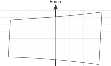
Constant Torque Energy Dissipator

Benefits of Rotational Friction Dampers
- Low cost of device and installation
- High energy dissipation per cycle
- Generally maintenance free
Disadvantages of Rotational Friction Dampers
- Must reach slip load to dissipate significant energy
- Large displacements cause significant changes in slip force as the angle changes.
- Cannot be used to dissipate wind loads (must set slip load higher than wind load)
Outcomes of poorly designed/manufactured Rotational Friction Dampers
- Friction force can change over time due to creep in the friction interface or creep in belleville washers
- Friction force can change over time due to corrosion or wearing of soft friction pads
- Insufficient thermal mass (too lightweight a damper) or poor thermal conduction can result in large temperature increases.
- Significant velocity or temperature dependence could exist in cases where plastics are used in the interface
- At larger angles the compressive forces can cause buckling of the links as the force required to cause the damper to slip increases.
Testing Methods
- Best practice test methods consist of 100% testing at full load and stroke.
- Testing should be done quasi statically in order to capture the change from static to dynamic friction as well as any variations in slip load in the damper travel.
Installation configurations
- Single diagonal
- Parallel (for larger loads)
- Chevron (at the top or in the diagonals)
- At beam/column connections
- Toggle
- Pinned connection is generally required
Tuned Mass Damper (TMD)
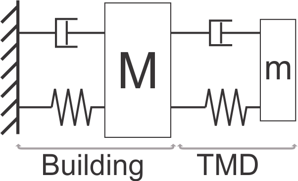
A tuned mass damper reduces the amplitude of displacements by storing some of the earthquake’s energy in a large moving mass connected by a spring element. The tuned mass is then connected to an energy dissipator (generally a viscous damper) in order to dissipate that energy (convert it to thermal energy). The TMD generally moves out of phase with the rest of the building, or more simply: moving left when the rest of the building goes right. The device is normally used to reduce the amplitude of vibration for a small range of problematic frequencies. It is commonly referred to as a harmonic absorber or harmonic oscillator in mechanical systems.
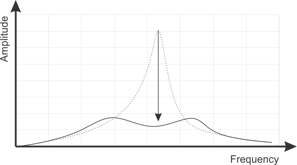
Damped Harmonic Oscillator
Benefits of TMDs
- Can be used for reducing the amplitude of harmonic vibrations due to wind
- Can be used for reducing the amplitude of harmonic vibrations due to earthquakes
Disadvantages of TMDs
- Must be tuned to the building stiffness and mass in order to remain in sync and efficient.
- Requires significant engineering expertise to design with
- Requires maintenance
- High initial and operating cost.
- Takes up valuable space on the highest (most valuable) floors of buildings, increasing overall cost.
Outcomes of poorly designed/manufactured TMDs
- Excessive friction in TMD connections resulting in moments and mismatch with engineering model
- Mismatch between cable stiffness and modeled stiffness resulting in different detuning
- Mismatch between mass and modeled stiffness
- See viscous dampers for outcome related to viscous damper manufacturing/design
Testing Methods for TMDs
- 100% testing of the viscous dampers used at full load and stroke. Viscous dampers must be tested at different velocities due to velocity dependence
- Cables and cable connections should be load tested to ensure appropriate tensile stiffness.
Installation configurations
- At top of the building using spherical connections
